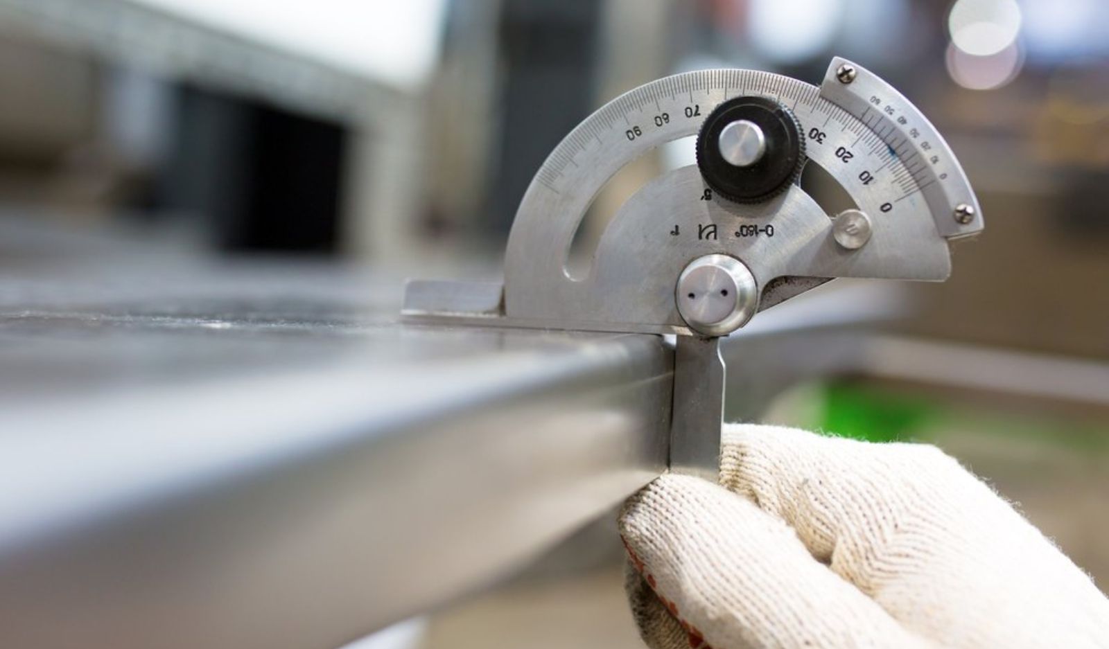
Steel shop drawings, Sydney-based or otherwise, don’t get much glory. They’re not the flashy architectural renders or the big structural calculations everyone signs off on with a flourish. But they translate an engineer’s design intent into something a boilermaker, a CNC machine, or a rigger can act on.
If they are wrong or incomplete, there will be RFIs, rework, blown schedules, and even safety risks on site.
The gap between design and reality
Structural engineers do brilliant work establishing member sizes, load paths, and connection criteria under standards like AS 4100. But their drawings are, by design, high-level. They tell you a universal beam spans between two columns, but they don’t tell you the exact cut length once mill tolerances are factored in, the root gap for a full-penetration weld, or the bevel on a stiffener plate.
A proper shop drawing package breaks the structural model down into two practical documents: shop assembly drawings for the people cutting and welding in the workshop, and site erection drawings for the crews putting it all together on-site. Everything flows from a coordinated 3D model. Workshop drawings, CNC files, erection plans, and field joint details all come from the same source, which is why accuracy at this stage matters so much. One mistake in the model doesn’t stay contained; it ripples out into every downstream document.
Compliance lives within shop drawings
In Australia, structural steelwork is classified into Construction Categories (CC1 through CC4) under AS/NZS 5131, based on a mix of building importance, the type of loading involved, and fabrication complexity. A simple farm shed sits at CC1. A hospital, a stadium, or a bridge with fatigue loading sits much higher up the scale.
The category dictates how much detail your shop drawings must include. Once you’re at CC2 or above, drawings need to spell out weld procedure specifications, flag where non-destructive testing is required, and tie mill certificate heat numbers back to individual part marks. Miss this, and you can end up with an invalid Fabricator’s Construction Data Report, which means big delays.
Avoiding RFIs at all costs
Nothing eats the budget and schedule like RFIs during fabrication. An RFI raised while steel is mid-cut on the shop floor stops the line. One raised during erection can ground a crane and idle a whole crew, plus every trade waiting behind them.
Good detailers catch these problems before anyone touches steel. Working in 3D modelling platforms, they run the structural layout against architectural plans, concrete and precast details, and MEP service routes, hunting for clashes. Anchor bolts that don’t line up with base plates, precast connection plates fouling steel cleats, ductwork that wants to run straight through a beam web all get found and fixed on screen, not discovered with a tape measure on site. Resolving a clash in the model costs a fraction of what it costs to fix once concrete’s poured or steel’s fabricated.
What can guarantee fabrication accuracy?
Modern fabrication shops run on CNC saws, plasma cutters, and automated drilling rigs, all of which are only as good as the digital files feeding them. Shop drawings generate the DSTV/NC data that tells that machinery exactly where to cut, drill, notch, and bevel. Accurate drawings mean flawless machine code and millimetre-accurate output. Sloppy drawings mean sloppy steel, no matter how good the machine is.
This shows up in a few key areas:
- Cut lengths and coping
Every beam, column, and hollow section needs exact dimensions so it fits without forcing or on-site trimming.
- Bolt and hole specification
Clearance holes, slotted holes, hole diameters and grades all need to be spelled out precisely, so high-strength bolts go in clean.
- Weld details
Correct weld symbols, leg lengths, and prep bevels stop welders from under-welding (a safety risk) or over-welding (which distorts steel and burns labour hours for no benefit).
- Part marking and traceability
Every piece gets a unique mark linking it back to a material certificate, which matters both for compliance and for catching dodgy imported steel before it ends up load-bearing in your building.
Getting steel up safely and on schedule
All of that upstream accuracy pays off the moment steel arrives on site. Good erection drawings give riggers a clear playbook: framing plans, grid references, floor levels, column orientation, piece marks, and bolt access points. When the drawings are right, members drop into place, bolt holes line up across stacked connections, and there’s no need to re-ream holes or reach for an oxy-torch to make something fit.
Field welding is inherently harder to control than shop welding, and unsafe on-site welding, particularly onto unverified cast-in plates, has been flagged repeatedly as a contributor to serious structural failures. Accurate detailing pushes as much welding as possible into the controlled shop environment and leaves site connections bolted wherever practical.
Where field welding can’t be avoided, good drawings specify the access holes, backing strips, and preheat requirements needed to do it safely. Erection drawings also carry practical logistics info, like member weights and centre-of-gravity data that let a rigging team size cranes correctly and plan lifts properly, plus details on temporary bracing to keep a partially erected frame stable until decking, slabs, and permanent bracing go in.
Ensuring steel detailing Sydney can trust
Shop drawings are where design intent either survives contact with reality or falls apart. Projects that treat detailing as an engineering discipline consistently see fewer RFIs, fewer site surprises, and steel that goes together the way it was supposed to the first time.
If you want your next steel project to run the way it’s meant to, namely on budget and schedule, without a crane sitting idle while someone argues over a bolt hole, it starts with getting the shop drawings right. Chat with our expert team at Steel Fabrication Services today.